

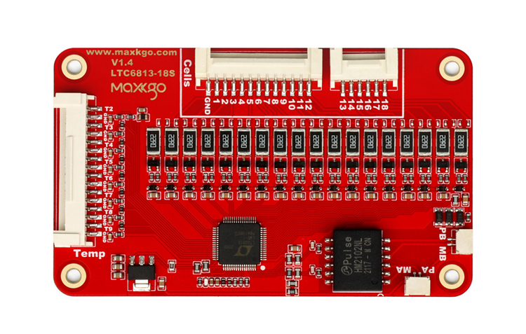
When you design a high-voltage battery pack, cell-level monitoring becomes critical for safety, balancing, and reliable operation. The LTC6813 battery management board gives you a modular way to monitor multiple cells while connecting slave boards through an isolated ISOSPI communication interface. MAXKGO’s LTC6813 slave BMS board supports 5–18 cell monitoring per board and battery applications within 150V, making it suitable for electric mobility, robotics, AGV systems, and energy storage. Instead of forcing every battery configuration into one fixed BMS architecture, you can build a scalable system around your actual series-cell requirements.
Why Choose an LTC6813 Battery Management Board?
A modular BMS can simplify battery system design when you need different cell counts or higher system voltages. MAXKGO developed this LTC6813 slave board for use with its MKBMS platform, which is compatible with ENNOID firmware.
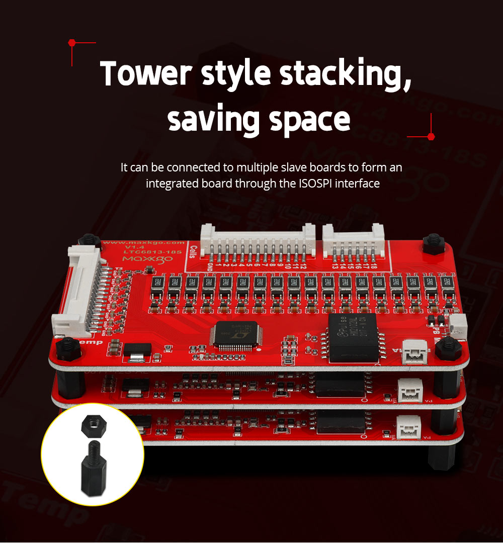
The board monitors individual cells and communicates with the master system through daisy-chain ISOSPI communication. This approach allows you to expand the monitoring architecture while maintaining electrical isolation between system sections.
Key capabilities include:
- 5–18 cell-level monitoring per board
- Support for Li-ion, lithium polymer, and LiFePO4 batteries
- 1.2 mV voltage measurement accuracy
- Operating temperature from -40°C to 120°C
- Sleep-mode power consumption of approximately 6 µA
- 33 Ω balance resistors with up to 0.125 A balancing capacity
- Scalable and isolated design rated for 1000 VDC+
- 1 onboard temperature channel plus up to 8 additional sensor interfaces depending on configuration
These specifications make the board relevant when you need a high voltage battery monitoring board rather than a basic battery protection circuit.
LTC6813 Slave Board Features for Modular BMS
The LTC6813 architecture works particularly well when your battery pack requires several monitoring boards.
Cell Monitoring and Battery Protection
The board supports core BMS functions through the MKBMS system, including:
- Overcharge protection
- Over-discharge protection
- Temperature protection
- Thermal management
- Cell balancing
- Battery pack capacity detection
- Battery internal resistance detection
- Battery health monitoring
You can therefore combine the LTC6813 slave board with a master controller to create a modular battery management system board for different battery configurations.
ISOSPI Communication and Daisy-Chain Expansion
For larger battery packs, communication architecture matters as much as cell measurement. The LTC6813 platform uses ISOSPI to connect slave boards and integrated boards with the master BMS.
This daisy chain BMS board configuration lets you distribute cell monitoring across multiple boards. For uneven series-cell counts, MAXKGO specifies that the last slave board in the daisy chain should be the board with one fewer connected cell.
15S, 18S and 36S Battery Configuration Options
You can select the number of slave boards according to the battery pack configuration. A single board can monitor 5–18 cells, while multiple boards can be combined for larger series configurations.
| Configuration | Typical Use | LTC6813 Board Approach |
|---|---|---|
| 15S | High-voltage mobility packs | One slave board |
| 16S | Lithium battery systems | One slave board |
| 17S | Custom battery packs | One slave board |
| 18S | High-voltage BMS applications | One slave board |
| 36S | Higher series-cell systems | Multiple slave boards |
| Up to 150V | High-voltage battery systems | Modular master-slave architecture |
For a 36S lithium battery BMS, for example, you can distribute cell monitoring across multiple LTC6813 boards rather than requiring a single board to handle every cell connection.
How to Integrate the LTC6813 BMS Module
If you are developing a custom battery pack, use the following workflow to reduce integration issues:
- Confirm the cell count
Determine whether your pack requires 15S, 16S, 17S, 18S, 36S, or another configuration. - Select the slave-board arrangement
Use the 5–18 cell monitoring capability of each board to determine how many LTC6813 slave boards you need. - Connect the ISOSPI communication chain
Build the master-to-slave and slave-to-slave communication path according to your MKBMS architecture. - Install temperature sensors
Account for the onboard temperature channel and additional sensor interfaces before final assembly. - Configure balancing and protection parameters
Set the required battery protection, balancing, current, voltage, and thermal-management parameters. - Test the complete battery pack
Verify cell voltage, temperature, communication, balancing, and protection functions under controlled operating conditions.
Applications for a High Voltage Battery Management System
The LTC6813 battery management architecture fits applications where accurate cell monitoring and scalable BMS control are important.
MAXKGO identifies applications including:
- Electric vehicles
- Electric patrol vehicles
- Handling robots
- Automatic forklifts
- AGV forklifts
- Electric two-wheelers
- Outdoor energy storage
- Home energy storage equipment
- Robotics
For these applications, you can combine the LTC6813 BMS module with a compatible master controller to build a distributed battery monitoring architecture.
Why Work With MAXKGO?
MAXKGO, belonging to Dongguan Daqianjin Technology Co., Ltd., has focused on high-performance BMS development since establishing the MAXKGO brand in 2021. The team originated from the FLIPSKY ecosystem and brings experience in electronic control and VESC-based development.
MAXKGO focuses on high-voltage, high-current BMS and drone ESC solutions. Its manufacturing process covers assembly, inspection, and quality control, while the company also provides technical support for battery management and electronic control products.
The brand’s product portfolio includes Hardware BMS, Smart BMS, Only Charge BMS, Smart Master Slave BMS, BMS Accessories, and Drone ESC products. This broader product structure allows you to source related battery management hardware from one specialized supplier.
FAQ
What is an LTC6813 battery management board?
An LTC6813 battery management board is a cell-monitoring board based on the LTC6813 battery monitoring platform. It measures multiple series-connected cells and communicates with a master BMS through an ISOSPI interface.
How many cells can the LTC6813 slave board monitor?
The MAXKGO board supports 5–18 cell-level monitoring per board. Multiple boards can be connected in a modular architecture for larger battery packs, such as 36S configurations.
Is the LTC6813 board suitable for high-voltage battery systems?
Yes. The MAXKGO design supports battery applications within 150V and provides scalable, isolated architecture rated at 1000 VDC+. You should still verify the complete system design, insulation, wiring, and protection requirements for your specific battery pack.
Conclusion
When you need scalable cell monitoring for a high-voltage lithium battery system, the LTC6813 battery management board provides a practical foundation for modular BMS development. With 5–18 cell monitoring per board, 1.2 mV accuracy, ISOSPI daisy-chain communication, balancing support, and compatibility with the MKBMS architecture, MAXKGO’s LTC6813 slave board can support battery systems ranging from 15S and 18S configurations to larger multi-board systems such as 36S.
Request Technical Support
If you are developing a 15S–18S, 36S, or up-to-150V battery pack, contact MAXKGO to confirm the required slave-board configuration, communication architecture, temperature-sensor setup, and master BMS compatibility before ordering.