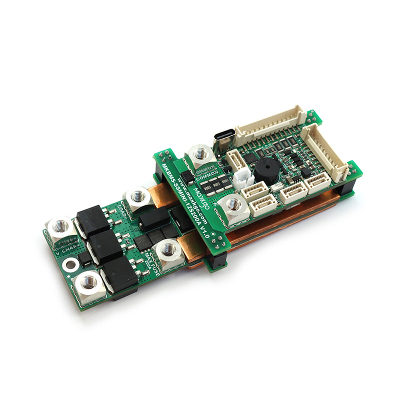

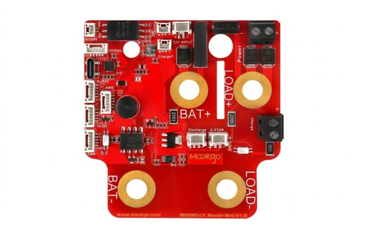
When you build a high-voltage battery pack, reliable cell monitoring becomes critical as the number of cells increases. An LTC6811 slave board gives you a practical way to monitor multiple battery cells while keeping your BMS architecture modular. MAXKGO’s LTC6811 12S Slave BMS Board supports 5–12 cells per board, communicates through ISOSPI, and can connect multiple slave boards in a daisy-chain configuration.
For EVs, e-bikes, robots and energy storage systems, you can scale the battery architecture according to the required series count instead of designing one oversized monitoring board. The product also provides cell balancing, temperature monitoring and protection functions for lithium-based battery packs.
Why Choose the MAXKGO LTC6811 Slave Board?
MAXKGO developed its BMS business from practical experience in high-performance electric mobility and electronic control. The brand originated from the FLIPSKY team in 2017 and officially established MAXKGO in 2021 to focus on high-voltage and high-current BMS solutions.
The LTC6811 slave board uses a modular architecture based on the LTC6811 battery monitoring platform. You can combine it with a compatible master board and additional slave boards through the ISOSPI interface.
Key specifications include:
- 5–12 cell-level monitoring per slave board
- 1 + 4 temperature channels
- 1.2 mV accuracy
- 6 μA sleep-mode power consumption
- -40°C to 120°C operating range
- 33 Ω balance resistors on all channels
- 0.125 A balance capacity
- Scalable and isolated 1000 VDC+
- Aluminum-alloy PCB construction for improved heat dissipation
- Molex SL horizontal connectors for balance and temperature
These specifications make the board suitable when you need detailed battery-cell data without abandoning a scalable BMS structure.
Modular 12S BMS with ISOSPI Communication
A conventional single-board BMS can become difficult to scale when your battery pack requires a higher series count. MAXKGO addresses this through a modular battery management system architecture.
The LTC6811 slave board communicates with the master through ISOSPI. Multiple slave boards can therefore form a larger battery monitoring system while each board handles a defined group of cells.
For example:
| Battery Pack | Slave Boards | Configuration |
|---|---|---|
| 23S | 2 | 12S + 11S |
| 27S | 3 | 9S + 9S + 9S |
| 29S | 3 | 10S + 10S + 9S |
| 30S | 3 | 10S + 10S + 10S |
| 35S | 3 | 12S + 12S + 11S |
This approach works well for applications where you need a 12S lithium battery BMS today but may require a higher-voltage battery architecture later.
Battery Protection and Cell Monitoring Functions
The board forms part of the MKBMS architecture, which provides more than basic voltage measurement. You can use the system for battery protection, balancing and operating-condition monitoring.
The supported functions include:
- Überladeschutz
- Over-discharge protection
- Temperaturschutz
- Wärmemanagement
- Erkennung der Akkukapazität
- Erkennung des Innenwiderstands der Batterie
- Cell balancing
- Überwachung des Batteriezustands
- Strom- und Spannungsschutz
- Programmable CAN bus integration through the MKBMS system
The system supports Li-ion, lithium-polymer and lithium-phosphate batteries, making it suitable for different battery chemistry requirements.
Real-World Application Scenarios
You can integrate this modular BMS architecture into applications such as:
- Electric vehicles and mobility vehicles
- E-bikes and electric two-wheelers
- Handling and AGV robots
- Automatic forklifts
- Electric patrol and sightseeing vehicles
- RV battery systems
- Energiespeicher im Freien
- Energiespeichergeräte für zu Hause
- Robotic power systems
For example, if your robot battery requires a 30S configuration, you can use three LTC6811 slave boards configured as 10S + 10S + 10S rather than forcing all cells onto one monitoring board.

How to Build a Scalable LTC6811 BMS
If you are evaluating this LTC6811 BMS board for a new battery project, follow these steps:
- Determine your battery series count. Define whether your pack requires 12S, 23S, 30S, 35S or another configuration.
- Divide the cells between slave boards. Each board supports 5–12 monitored cells.
- Select a compatible MKBMS master board. The master manages communication and overall system functions.
- Connect the boards through ISOSPI. Use the daisy-chain architecture to integrate multiple monitoring boards.
- Configure temperature monitoring and balancing. Connect the required temperature sensors and configure cell-balancing parameters.
- Validate the complete battery pack. Test voltage measurement, protection, balancing and thermal behavior before deployment.
This process helps you match the BMS architecture to your actual battery configuration instead of selecting a fixed board only by its nominal series count.
MAXKGO Quality and Engineering Support
MAXKGO focuses on high-performance BMS and ESC solutions for electric mobility, Robotik, drones and intelligent power systems. Its product development process includes R&D, manufacturing, quality control and real-world testing.
The company also provides factory, production-line and equipment documentation, together with certificate documentation presented through its official company materials. This gives you useful background when evaluating a BMS supplier for a professional project.
For engineering teams, MAXKGO’s product range also includes hardware BMS, Intelligentes BMS, smart master-slave BMS, BMS accessories and drone ESC products. This broader product portfolio can support projects that require battery management and electronic control technologies from the same supplier.
FAQ
1. How many cells can one LTC6811 slave board monitor?
One board supports 5–12 cell-level monitoring. You can connect multiple slave boards through ISOSPI when your battery pack requires a higher series count.
2. Can I use the board for a 30S battery pack?
Ja. A 30S configuration can use three LTC6811-12S boards, with each board monitoring 10 cells.
3. What batteries does the LTC6811 BMS support?
The MKBMS architecture supports Li-ion, lithium-polymer and lithium-phosphate batteries, as well as most common lithium battery types.
Conclusion
If you need a scalable solution for cell-level monitoring in an EV, e-bike, robot or energy storage battery pack, the LTC6811 slave board provides a modular approach based on 5–12 cell monitoring, ISOSPI communication and daisy-chain expansion. With configurations such as 23S, 30S and 35S, you can adapt the MKBMS architecture to different battery designs while retaining cell protection, balancing and temperature-monitoring capabilities.
Get Your LTC6811 BMS Solution
Need to confirm whether the LTC6811 slave board fits your battery pack? Contact MAXKGO with your battery series count, cell chemistry, target voltage and application requirements. Our team can help you evaluate the appropriate master-slave BMS configuration and provide product details for your project.